August 16, 2010
Instruction of
CADLIVE Converter
1.
Top page of the CADLIVE Converter
2. Conversion of a KEGG file to a CADLIVE file
3. Conversion of a PPI file to a CADLIVE file.
3.1. Upload PPI tab delimited file
4. Conversion of a regulation file to a CADLIVE file
4.2. Upload Regulation tab delimited file
5. Conversion of a CellDesigner file to a CADLIVE file
5.1. Upload CellDesigner XML file
6. Conversion of a BioCyc file to a CADLIVE file
7. Layout of the network map written in a CADLIVE file
7.1. Cut off small isolated networks
8. Visualization of a network map
9 Merge of multiple CADLIVE files
The converter is a client and server model.
Recommended environment: Windows XP, Internet Explore 8
Access the URL site:
http://kurata23.bio.kyutech.ac.jp/CADLIVE_CONVERTER/index.html
1. Top page of the CADLIVE Converter
The top page is displayed in Fig. B.1. Users select a function from MENU.
Users need to turn on setting of javascript.
In all functions, after “Conversion finished” is displayed, users can download the converted file.
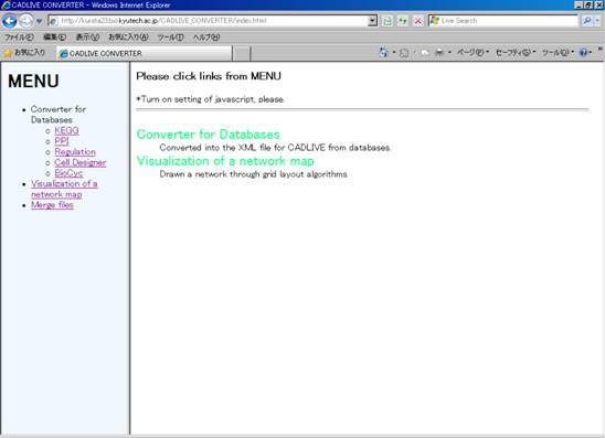
Fig. B.1 Top page of the CADLIVE Converter
2. Conversion of a KEGG file to a CADLIVE file
Click KEGG.
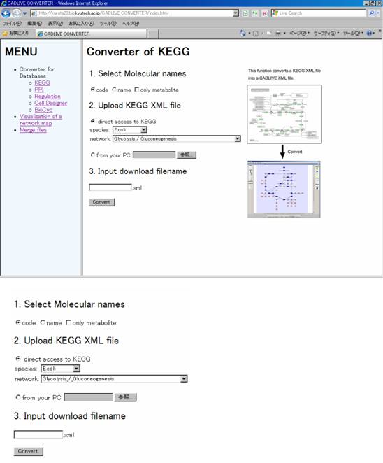
Fig. B.2 A page for conversion of a KEGG file to a CADLIVE file.
2.1. Select Molecular name
Radiobuttons: “code” and “name” select molecular name. “code” indicates that the molecular names in the file converted from KEGG are named the KEGG code names (cpd or eco, etc.). “name” indicates that the molecular names in the converted file are named general names (such as H2O and glnK). All metabolite names can be converted, while the conversion of general (common) description names is restricted to eco (E. coli) and sce (yeast).
Clicking on the checkbox of “only metabolite” generates the file of metabolic pathways without any enzymes; otherwise, the pathways contain their associated enzymes.
2.2. Upload KEGG XML file
The CADLIVE Converter selects either the download of a KEGG xml file from the KEGG site or the upload of it from their PC.
direct access to KEGG: the server downloads a KEGG xml file to convert.
from your PC: Users upload the KEGG xml file that has been saved in users’ PC.
2.3. Input download filename
Users input the file name to download.
By clicking the “Convert” button, the conversion of the selected file starts.
3. Conversion of a PPI file to a CADLIVE file.
Click PPI.
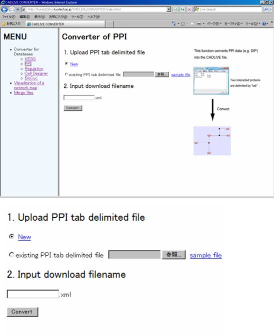
Fig. B.3 A page for conversion of a PPI file to a CADLIVE file.
3.1. Upload PPI tab delimited file
The radiobutton selects either the direct input of a PPI network on the server or the upload of it from users’ PC.
When users directly input a PPI network on the server, select the “New” button and write PPIs in the text area (Fig. B.4). When users input an existing PPI file, select the “existing PPI tab delimited file” button to upload it.
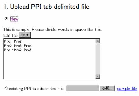
Fig. B.4 A text box for direct input of a PPI network.
3.2. Input download filename
Users input the download filename.
By clicking the “Convert” button, the conversion of the selected file starts.
4. Conversion of a regulation file to a CADLIVE file
Click Regulation.
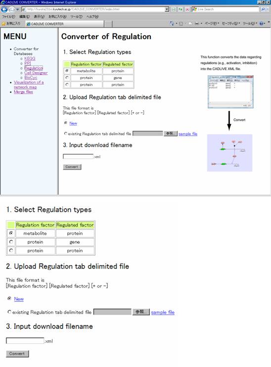
Fig. B.5 A page for conversion of a regulator-reaction file to a CADLIVE file.
4.1. Select Regulation types
Set the type of regulation-reaction models. For example, if the “Regulation factor” is protein and “Regulated factor” is gene, it means the transcriptional regulation.
4.2. Upload Regulation tab delimited file
Upload the file in the same manner as a PPI network.
4.3. Input download filename
Users input the download filename.
Clicking the “Convert” button starts the conversion of the selected file.
5. Conversion of a CellDesigner file to a CADLIVE file
Click CellDesigner.
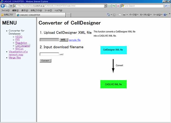
Fig. B.6 A page for conversion of a CellDesigner file to a CADLIVE file.
5.1. Upload CellDesigner XML file
Users upload an xml file of CellDesigner from users’ PC.
5.2. Input download filename
Users input the download filename.
Clicking the “Convert” button starts the conversion of the selected file.
6. Conversion of a BioCyc file to a CADLIVE file
Click BioCyc.
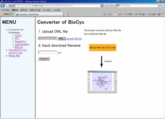
Fig. B.7 A page for conversion of a BioCyc file to a CADLIVE file.
6.1. Upload OWL file
Users upload an owl file of BioCyc from users’ PC.
6.2. Input download filename
Users input the download filename.
Clicking the “Convert” button starts the conversion of the selected file.
7. Layout of the network map written in a CADLIVE file
Click Visualization of a network map.
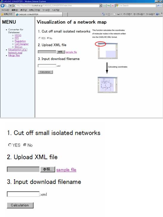
Fig. B.8 Grid layout of the converted network file written in the CADLIVE format.
7.1. Cut off small isolated networks
Network files often have some isolated components. If user extract just the core network that has the largest number of nodes, select the “Yes” button; otherwise, select the “No” button.
7.2. Upload XML file
Users select an xml file of CADLIVE from users’ PC to calculate the coordinates of molecular nodes for visualization of the network.
7.3. Input download filename
Users input the download filename.
Clicking the “Calculation” button starts calculating the coordinates of the nodes in the selected network file.
8. Visualization of a network map
There are two ways for drawings: SVG and BNV.
SVG:
To immediately confirm the network map
calculated by the grid layout on a web browser, the SVG format is built
according to the CADLIVE graphical notations. This does not display the
molecular names. Details of operations are shown at http://www.w3.org/Graphics/SVG/
BNV
To visualize a large-scale network with molecular names, BNV is developed based on OpenGL. BNV implements convenient functions for users such as zoom in/out, translation, spread/shorten the network, and saving as a bmp file.
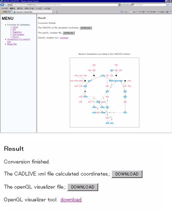
Fig. B.9 Visualization of the network layouted by the Grid Layout program
The network map is drawn as the SVG map format according to the CADLIVE graphical notations as shown in Fig. B.9. The layout is performed by our Grid Layout program.
Three files can be downloaded to users’ PC.
1. The CADLIVE xml file calculated coordinates: Users can download the CADLIVE xml with the calculated coordinates of the nodes. Users can display it using the CADLIVE Network Constructor.
2. The openGL visualizer file: Users can download the BNV file named “output.BNV”.
3. OpenGL visualizer tool: Clicking the link opens the instruction window of how to use BNV. Users download the BNV tool. Once BNV is installed, users do not have to click this button again.
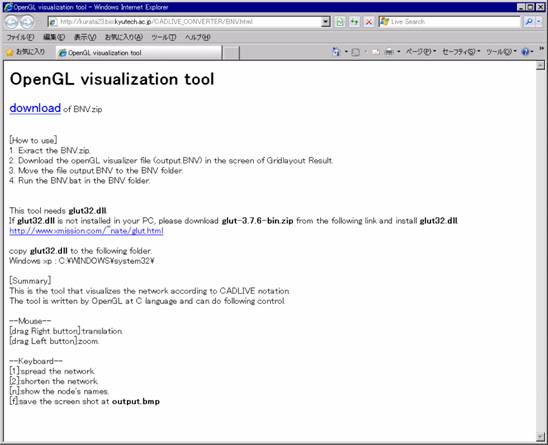
Fig. B.10 Instruction window for BNV explanation
In Fig. B.10 the window shows how to download, install and execute the BNV tool.
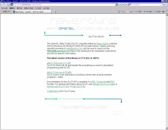
Fig. B.11 Download site for a glut file
Users download and decompress glut-3.7.6-bin.zip, and copy gult32.dll into C:\WINDOWS\system32\ (Windows XP).
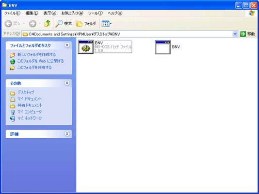
Fig. B.12 BNV folder
There are two files in the decompressed file of BNV.zip (Fig. B.12). Users copy the output.BNV into this folder. Double-clicking on BNV.bat runs BNV to display the map (output.BNV) as shown in Fig. B.13.
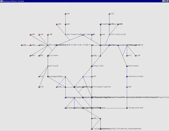
Fig. B.13 The result of BNV
9 Merge of multiple CADLIVE files
Click Merge files.
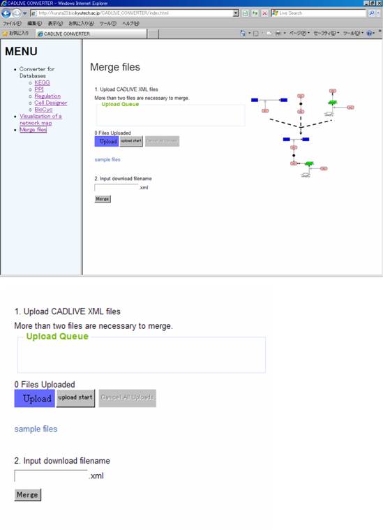
Fig. B.14 A page for merging multiple CADLIVE files simultaneously
9.1. Upload CADLIVE XML files
[Upload]
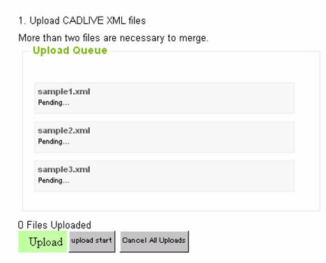
Users refer more than two CADLIVE files to select. The selected files are displayed in Upload Queue.
*Users must select at least two files.
[upload start]
The displayed files in Upload Queue are uploaded. Once those files are upload, they cannot be canceled. If users want to cancel, just click “Merge files”.
[Cancel of Uploads]
This button cancels the displayed files.
9.2 Input download filename
Users input the name of the merge file.
Clicking the “Merge” button merges the selected files.